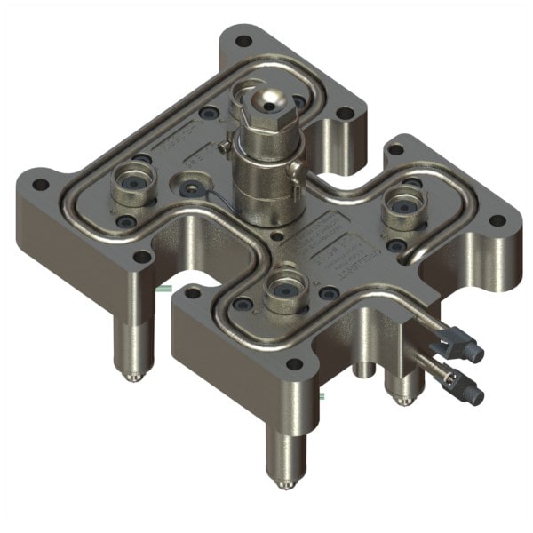
Hot Runner System Hot Runner Manifold 4 Drop Manufacturer from Mumbai
Push Molding Going Green, Moldex3D Introduced Advanced Hot Runner Module Blog Moldex3D
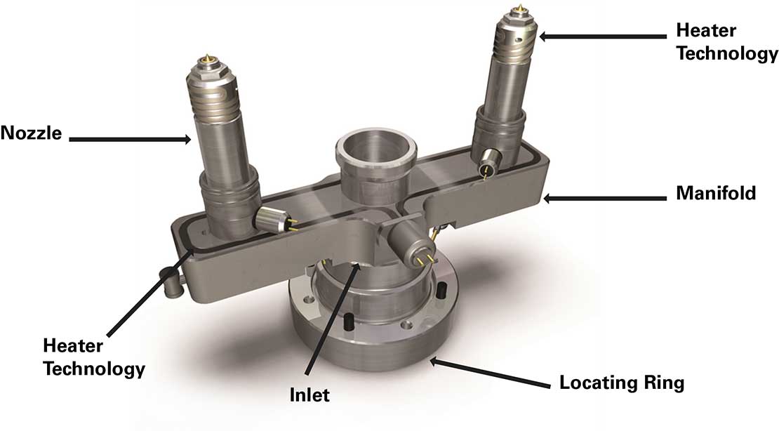
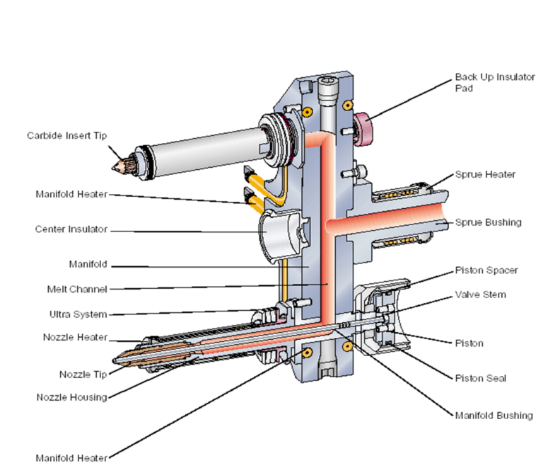
The hot runner system consists of a manifold, which is a heated block with multiple channels, and a series of nozzles that deliver the molten plastic directly into the mold cavities. The channels and nozzles in the hot runner system are heated to maintain the plastic in a molten state throughout the injection molding process.
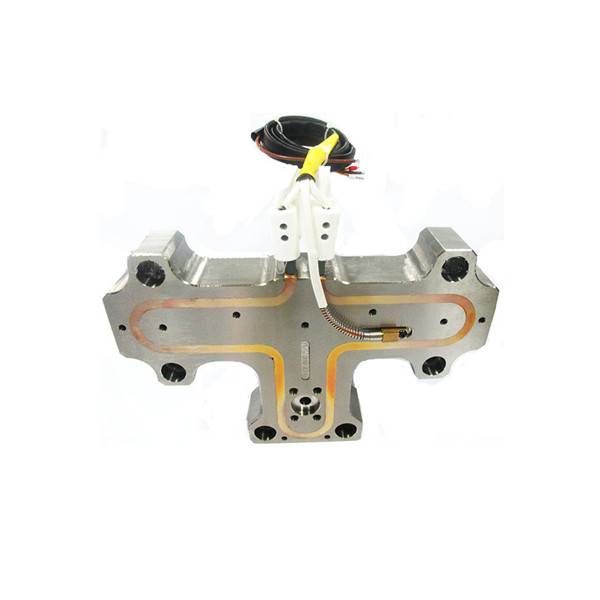
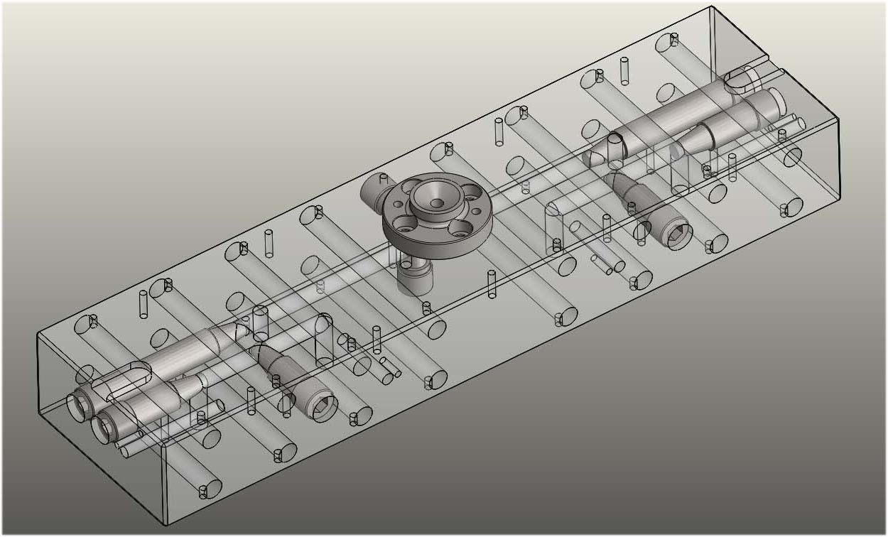
Multicavity hot runner manifold block with two layers runner
General Hot Runner Information Hot Runner Product Handbook v 19.4 Cooling Recommendation - HT Style Section-View Details HT Cap TS HT-S6 Sidegate COOLING SLOT OR CHANNEL: MIN FLOW RATE 5 L/MINUTE A B 1-1.5 ∅ 2-3 ∅ A B 1-1.5 ∅ 2-3 ∅ A B 1-1.5 ∅ 2-3 ∅ A Note 1-1.5 ∅ Position the cooling center- line at the mid point of the seal.

Hot Runner System Hot Runner Manifold 4 Drop Manufacturer from Mumbai
Plates Hot Half System Mould Design Recommendations 1.0 Plate Requirements Manifold and Back Plate Material • High strength material must be used for the plates. • Minimum plate material is 1.2311/1.2312, 30HRC, 800MPa Yield Strength. Manifold and Back Plate Thickness
Hot Runner Tooling Injection Molding LHR Technical Service
Pronto Hot Runners. With over 100 available manifold layouts and 14 different gating styles, you can spec the perfect parameters for your operation. Learn More.. Husky customers have access to a wealth of information tools including hot runner guides, CAD design tips, plate calculators, nozzle libraries, project tracking, gate cooling, and.
Hotrunner components embrace innovation
That will prevent heater shorts and promote heater life.Keep barrel nozzle temperature below melt temperature. The barrel nozzle temperature should be set 25 deg F below the melt temperature, which then becomes the starting point for the manifold temperatures. Hot runner temperatures typically ramp downward from the runner bushing to the tip.
Hot runner manifold EMP E.M.P. srl
Depending on the type of resin and the design of the hot runner the inlet component may be heated in order to optimize the molding process. Manifold - The manifold enables the flow of resin into different nozzles and injection points (gates). Manifolds are normally used where multiple cavities are injected or where more than one nozzle/gate.
hot runner design
How Hot Runner System Works. The hot runner molds are made up of two plates that are heated with a manifold system. The function of the manifold is to maintain a consistent temperature. This is done by keeping the molten thermoplastic in the runners at the same temperature as the temperature of the heating cylinder.
What is a hot runner? Mold Masters
Manifold plate design. The manifold plate of the hot runner has three primary operations to perform. The first one is to provide support to other components. The second is to offer a surface area for backing plate bolts. At last, the manifold plate also works as backup support for the cavity plate.
mold hot runner manifold manufactures I type balance designWMFI0001
Hot runner manifold design optimizes the distribution of molten plastic, reducing waste and improving product quality. Water manifolds maintain mold temperatures, enhancing consistency and efficiency in the molding process. Together, these components are essential for efficient and high-quality plastic part production.

ホットランナー金型システム Khuôn Duy Tân
Design flexibility and customized solutions Hot runner components. Nozzles are the hot runner components designed to inject the plastic melt into the cavities. There are three main types of injection:. The main task of the hot runner manifold is to distribute the plastic material into different nozzles.
Hot runner Sositar
A hot runner mold system is a two-plate injection molding assembly that uses a runnerless heated manifold system and heated nozzles, managed by a temperature control system, to keep the thermoplastic in a molten state until it is finally injected into the cavities through temperature-controlled gates (drops) to form the final part where it is then cooled and ejected from the mold.
Hot runner manifold Eastern Plastics Injection Moulding and Hot Runner Solutions
How Hot Runner Manifold Design Influences Color Change. Another influence to color change with hot runners is the manifold design. This applies to any hot runner, regardless of nozzle or gating style. Manifold melt volume and shot count is a necessity for any hot runner application, with some manifolds containing more melt than others. That.

PolyFlow Hot Runner System Pre Wired Hot Runner Systems
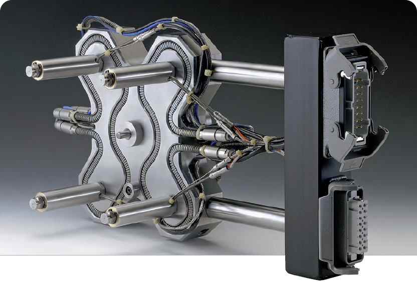
Bill Gunn, Husky Injection Molding Systems. Figure 2: Manifold plate with integral pocket. Proper design of the hot runner plates is critical to molding success. The hot runner plates must perform the function of a rigid and stable support while being exposed to high mechanical loadings from both the hot runner components and the molding machine.

Hottechs Hot Runner
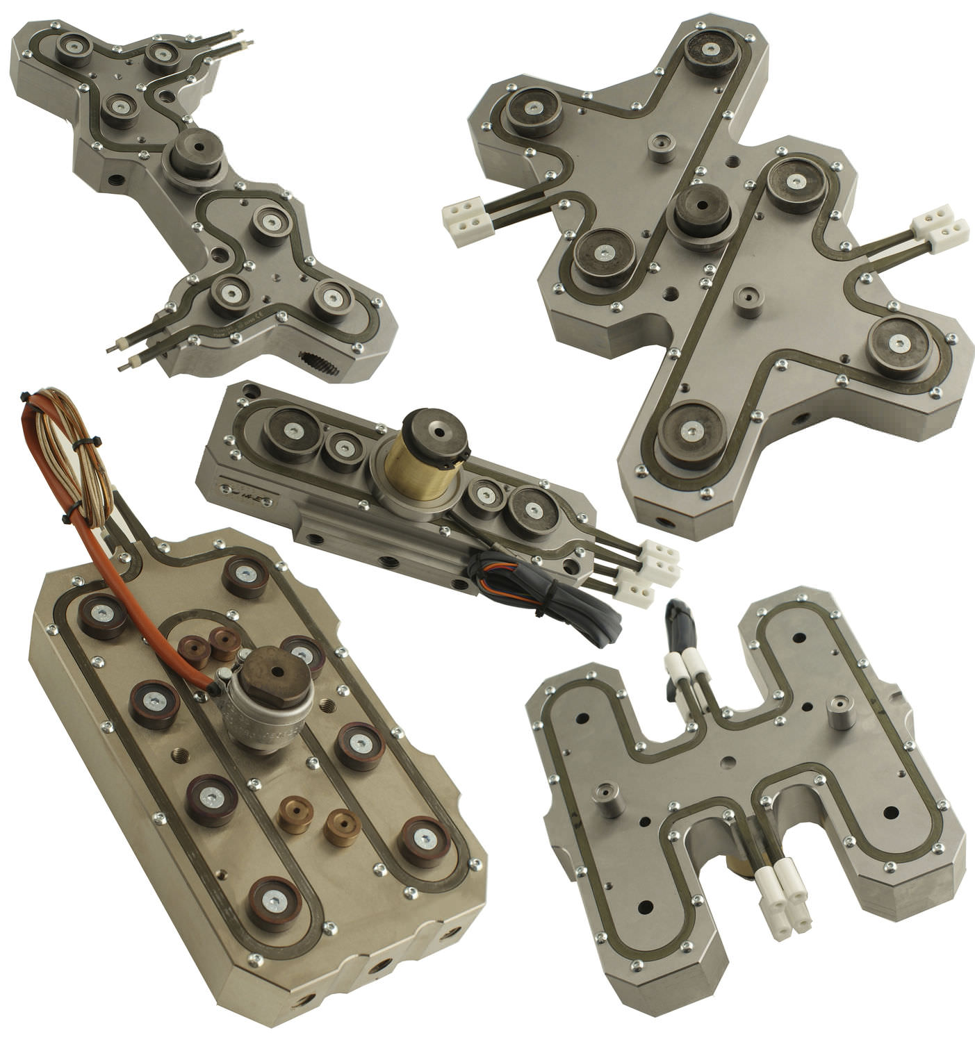
2 OPEN HOT RUNNER SYSTEMS Manifold systems Different manifold versions can be selected for different applications, from partially or fully balanced to customer-specific special solu-tions. Flexible positioning of hot runner nozzles with a manifold make individualised mould design possible. We reserve the right to make technical changes. 07/18

Hot Runner Manifold Block Suppliers & Manufacturers in India
Pressed-in heaters on both sides guarantee optimum heat transfer to the manifold block. This results in homogeneous temperature distribution. Protected power connections - highly maintenance friendly. Steel and ceramic sleeves protect the power plug connections from damage. Mechanical cleaning of the manifold runners is easy and fast.
Hot Runner Replacement Parts and Products Polyshot
Manifold requirements also play an important role in initial system design implementation. Hot runner manifolds are available in an unlimited number of custom sizes with flexible drop locations. Manifold shapes and sizes are dependent on the number of mold cavities and spacing. Channel layouts must be balanced to achieve optimal flow conditions.
